A structure must be designed to resist all the loads expected to act on the structure during its service life. Under the effects of the expected applied loads, the structure must remain intact and perform satisfactorily. In addition, a structure must not require an inordinate amount of resources to construct. Thus, the design of a structure is a balance of necessary reliability and reasonable economy.
Wood products are frequently used to provide the principal means of structural support for buildings. Economy and soundness of construction can be achieved by using wood products as members for structural applications such as joists, wall studs, rafters, beams, girders, and trusses. In addition, wood sheathing and decking products perform both a structural role by transferring wind, snow, occupant and content loads to the main structural members, as well as the function of building enclosure. Wood can be used in many structural forms such as light-frame housing and small buildings that utilize repetitive small dimension members or within larger and heavier structural framing systems, such as mass timber construction, which is often utilized for commercial, institutional or industrial projects. The engineered design of wood structural components and systems is based on the CSA O86 standard.
During the 1980s, the design of wood structures in Canada, as directed by the National Building Code of Canada (NBC) and CSA O86, changed from working stress design (WSD) to limit states design (LSD), making the structural design approach for wood similar to those of other major building materials.
All structural design approaches require the following for both strength and serviceability:
Member resistance = Effects of design loads
Using the LSD method, the structure and its individual components are characterized by their resistance to the effects of the applied loads. The NBC applies factors of safety to both the resistance side and the load side of the design equation:
Factored resistance = Factored load effect
The factored resistance is the product of a resistance factor (f) and the nominal resistance (specified strength), both of which are provided in CSA O86 for wood materials and connections. The resistance factor takes into account the variability of dimensions and material properties, workmanship, type of failure, and uncertainty in the prediction of resistance. The factored load effect is calculated in accordance with the NBC by multiplying the actual loads on the structure (specified loads) by load factors that account for the variability of the load.
No two samples of wood or any other material are exactly the same strength. In any manufacturing process, it is necessary to recognize that each manufactured piece will be unique. Loads, such as snow and wind, are also variable. Therefore, structural design must recognize that loads and resistances are really groups of data rather than single values. Like any group of data, there are statistical attributes such as mean, standard deviation, and coefficient of variation. The goal of design is to find a reasonable balance between reliability and factors such as economy and practicality.
The reliability of a structure depends on a variety of factors that can be categorized as follows:
- external influences such as loads and temperature change;
- modelling and analysis of the structure, code interpretations, design assumptions and other judgements which make up the design process;
- strength and consistency of materials used in construction; and
- quality of the construction process.
The LSD approach is to provide adequate resistance to certain limit states, namely strength and serviceability. Strength limit states refer to the maximum load-carrying capacity of the structure. Serviceability limit states are those that restrict the normal use and occupancy of the structure such as excessive deflection or vibration. A structure is considered to have failed or to be unfit for use when it reaches a limit state, beyond which its performance or use is impaired.
The limit states for wood design are classified into the following two categories:
- Ultimate limit states (ULS) are concerned with life safety and correspond to the maximum load-carrying capacity and include such failures as loss of equilibrium, loss of load-carrying capacity, instability and fracture; and
- Serviceability limit states (SLS) concern restrictions on the normal use of a structure.
Examples of SLS include deflection, vibration and localized damage.
Due to the unique natural properties of wood such as the presence of knots, wane or slope of grain, the design approach for wood requires the use of modification factors specific to the structural behaviour. These modification factors are used to adjust the specified strengths provided in CSA O86 in order to account for material characteristics specific to wood. Common modification factors used in structural wood design include duration of load effects, system effects related to repetitive members acting together, wet or dry service condition factors, effects of member size on strength, and influence of chemicals and pressure treatment
Wood building systems have high strength-to-weight ratios and light-frame wood construction contains many small connectors, most commonly nails, which provide significant ductility and capacity when resisting lateral loads, such as earthquake and wind.
Light-frame shearwalls and diaphragms are a very common and practical lateral bracing solution for wood buildings. Typically, the wood sheathing, most commonly plywood or oriented strand board (OSB), that is specified to resist the gravity loading can also act as the lateral force resisting system. This means that the sheathing serves a number of purposes including distributing loads to the floor or roof joists, bracing beams and studs from buckling out of plane, and providing the lateral resistance to wind and earthquake loads. Other lateral load resisting systems that are used in wood buildings include rigid frames or portal frames, knee bracing and cross-bracing.
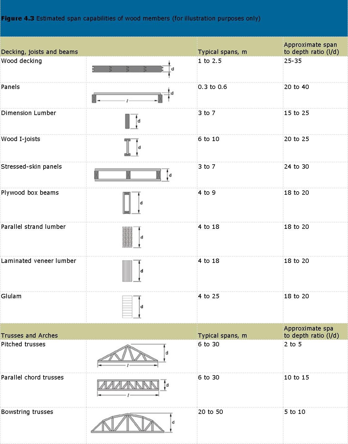
A table of typical spans is presented below to aid the designer in selecting an appropriate wood structural system.
Pour plus d'informations, consultez les ressources suivantes :
Introduction to Wood Design (Canadian Wood Council)
Wood Design Manual (Canadian Wood Council)
CSA O86 Engineering design in wood


