Welcome to the new CWC Digital Resource Hub

[dynamic_title_articles_tags]
266 results found...
Sort By Dropdown Icon
Article

Most building envelope / building enclosure failures can be traced back to water. If we can learn to manage (rather than control) water in the building envelope/enclosure, we will have learned how to master an essential component of building science. We have deliberately chosen the term “manage” since it implies using the laws of nature to our advantage rather than attempting to conquer nature by brute force. Attempts to control water movement by face sealing walls, for example, require perfect materials, workership and maintenance,  commodities which are rarely available to us. Management on the other hand implies designing assemblies which can deflect, drain, store and dry moisture, using materials suited to the various microclimates which the outside climate, inside climate and wall construction provide.

In the building science context, the transport of water can be divided into three main categories:

  1. water transported through porous materials by water vapour diffusion, either from the inside or from the outside
  2. water vapour carried by moving air, and
  3. liquid or bulk water from rain, wind driven rain, melting snow, groundwater driven by gravity or kinetic energy

Water Vapour Diffusion

The rate of water vapour diffusion through a porous material is determined by a water vapour pressure gradient (or water vapour molecule concentration gradient) from one side to the other side of the material, and the permeance of the material given in “perms” in the U.S. or ng/pa.s.m2 in Canada (1 perm = 57 ng/pa.s.m2). The greater the water vapour pressure gradient, the greater the rate of diffusion. The greater the permeance, the greater the rate of diffusion.

These Durability Notes will focus on two types or categories of vapour diffusion: Water Vapour Diffusion from Inside, and Water Vapour Diffusion from the Outside. Additionally, categories include air leakage from the inside, exterior moisture/wetting and drying potential to the outside and to the inside. 

Water vapour diffusion from the inside is typically a wintertime phenomenon in cold climates, and can be managed by either maintaining the indoor relative humidity (rh) at a safe level (CMHC recommends a maximum of 40 to 50% indoor rh in the winter time). 
Water Vapour Diffusion from Outside is typically a late spring, summer or early fall phenomenon in a cold climate, and is usually of a specific category known as “solar-driven moisture”  when it presents moisture related problems. Solar driven moisture is happens when a porous cladding capable of absorbing and storing water (such as a brick veneer or wood siding) becomes wet due to a rain event, and then the sun shines on the wall cladding, heating it up often up to over 40ºC above the ambient air temperature, resulting in very high vapour pressures within the porous cladding, which then drives the water vapour into the wall. This phenomenon is most common on east and west elevations as these receive the maximum solar exposure in the summer.  Some common methods for avoiding this phenomenon involve using non-absorptive claddings such as vinyl siding or non-absorptive treatments on wood siding, by providing a well vented cavity vented to the outside behind brick veneers and other absorptive claddings, or by providing shading to east and west facing walls.
Air Leakage Transported Moisture from Inside is typically a wintertime phenomenon in cold climates, and can typically cause greater moisture related problems than water vapour diffusion. This phenomenon occurs when warm, moisture laden interior air is not prevented from leaking into a building assembly, and comes in contact with a cold, low permeability material which is at a temperature below the dew point temperature of the indoor air, where the moisture then condenses on the cold surface. If this moisture cannot be drained away and accumulates it may result in mould, rot, corrosion etc. This phenomenon can be prevented in several ways and combinations of ways, including the use of continuous interior air barriers (eg. taped drywall with all penetrations sealed, polyethylene air barriers/vapour retarders), by designing the assembly such that the first air-tight material in the assembly is at a temperature above the dew point temperature of the indoor air (eg.using  Insulative exterior sheathing), by using materials which are not moisture susceptible, and by maintaining a safe indoor wintertime relative humidity.
Exterior Moisture/Wetting (Rain) can present problems either when the water can penetrate/leak into an assembly where it comes in contact with and accumulates in/on moisture-susceptible materials, (made worse by rain in combination with wind, called wind-driven rain), or when the rain comes in contact with susceptible claddings for extended periods of time (again made worse by wind-driven rain). Walls facing the prevailing wind for a given region are at highest risk. Rain falling straight down without wind can be relatively easily dealt with by providing adequate roof-overhangs, eaves troughs and flashings, and by using cladding materials which are not susceptible to moisture related problems. Wind-driven rain is more difficult to deal with, but the same approaches apply. In addition, it should always be assumed that at some point in time, water will penetrate into an assembly, and it must be allowed to get back out by the use of flashings and drainage planes, by allowing drying to both sides if possible, and by using materials not susceptible to moisture related damage.
Drying Potential to the Inside and to the Outside can occur in building assemblies. However, to avoid deterioration of the wall or wetting of the building interior, moisture from within the assembly will need to effectively dry to the inside and/or to the outside. Excess moisture can move into the assembly from the interior or from the exterior. Moisture can also be built into the assembly when wet materials or components are used at the time of construction. Assemblies that get wet and that are able to dry are generally more durable than otherwise.

Deterioration Mechanisms

  • Mould
  • Rot
  • Corrosion
  • Freeze-thaw

Understanding the Simulated Durability Analysis Results


WUFI Hygrothermal Modeling and Field Experience Rating
This represents the result of a combined analysis of field experience and comprehensive WUFI analyses on the selected wall assembly in each of the 5 climate conditions:

dark green square that represents High Pass rating for durabilityDark Green: HIGH PASS

Field: Good experience under wide range of conditions
Physics: Well understood physics and sound basis for design
Hygrothermal Modelling: Simulations support field experience and expectations from physics
green square that represents a Pass rating for durabilityLight Green: PASS

Field: Good experience under normal conditions
Physics: Well understood physics; expected to  be slightly sensitive to details and workmanship
Hygrothermal Modelling: Simulations support field experience and expectations from physics
yellow square that represents conditional Pass rating for durabilityYellow: CONDITIONAL PASS

Field: Acceptable experience under  normal conditions; more sensitive to details, workmanship, and microclimates
Physics: More complex physics, expected to be more sensitive to details and workmanship
Hygrothermal Modelling: Field experience and physics can only be explained by expert modellers
orange square that represents a Fail rating for durabilityOrange: CONDITIONAL FAIL

Field: Demonstrated to be risky in certain situations
Physics: More complex physics, expected to be VERY sensitive to details and workmanship
Hygrothermal Modelling: Field experience and physics can only be explained by expert modellers

Building Codes have air barrier and rain intrusion requirements that are assumed to be complied with.  Failure to meet code requirements can result in walls that are not durable.

It is important to note that all the assemblies were simulated assuming no air leakage and no water intrusion/leakage.  As a result, the WUFI durability simulations do not consider the limited drying potential associated with the use of low permeance sheathing materials when combined with poor air barrier installation and flashing details.

Please see WUFI Assumptions for more details.

Outboard to Inboard Ratio Compliance
This scale represents the result of an outboard to inboard analysis on the wall assemblies using low permeance exterior sheathings:

green squarePASS – Green indicates that the wall meets the climate’s required minimum ratio
red squareFAIL – Red indicates that the wall does not meet the climate’s required minimum ratio and the outboard sheathing’s permeance must be examined to verify Code compliance
Article

Software: WUFI Pro 5.1 (1-d)

Orientation:  Each assembly was modeled facing the direction of prevailing wind-driven rain and maximum solar exposure as follows, for a vertical wall and building height up to 10m tall

Location: Vancouver (east), Edmonton (west), Toronto (east), Montreal (south-west), St. John’s (south-east). WUFI analysis considers the climatic variables of a specific location for an accurate hygrothermal assessment. The hygrothermal performance of assemblies in locations not listed on EffectiveR.ca should be analyzed by a qualified professional to ensure accurate results. 

Rain load: R1 (0), R2 (0.07 s/m) default settings

Surface Transfer Coefficients:

Exterior surface
Heat resistance: 0.0588 (m2K/W), external wall, wind dependant
Sd value: No coating
Short wave radiation absorptivity: 0.68 (red brick)
Long wave radiation emissivity: 0.90
Adhering factor of rain: 0.7 according to inclination and construction type

Interior surface
Heat resistance (m2K/W): 0.125 (External wall)
Sd value: User defined 0.3 (approximates two coats of latex paint)

Initial Conditions:

Initial moisture in component: Constant across component
Initial temperature in component: Constant across component
Initial relative humidity: 0.80
Initial temperature: 20ºC

Numerics: Each wall modeled for a simulation period of 5-9 years

Mode of calculation:
Heat transport calculation, moisture transport calculation
For thermal conductivity use temperature and moisture dependency

No hygrothermal special options

Numerical parameters
Increased accuracy
Adapted convergences

No adaptive time step control

Geometry
Cartesian

Outdoor climate: Cold year when an option, from map/file, (using analysis function for choosing worst case orientation)

Indoor climate:
User defined sine curve parameters
Temperature, mean 210C with +/- 20C (day of maximum 06/03)
Relative humidity, mean 45% with +/- 15% (day of maximum 08/16)

Material assumptions:

Generic materials (WUFI 5.3 Material Database):
Red matt clay brick
Fibre cement sheathing board
Spruce (for wood siding)
Acrylic Stucco
EPS
Air layer, without additional moisture capacity
Asphalt impregnated paper (30 min paper)
Oriented strand board (650 kg/m3)
Plywood (USA)
Vapour retarder (0.1 perm)
Gypsum board (USA)
Sprayed Polyurethane Foam; closed cell
Polyisocyanurate Insulation
Metall-Foile (for foil facing on Polyisocyanurate)
Roxul RockBoard
Spun Bonded Polyolefin Membrane (SBP)

Modified generic materials:
R19, R21 and R24 Fibre glass batt
Fibre Glass Batt (WUFI 5.3 North American Material Database) modified density and k-value according to manufacturer data to represent R-21 and R-24

3/4lb spray foam
Spray polyurethane foam; Open cell (WUFI 5.3 North American Material Database) modified bulk density, thermal conductivity, water vapour diffusion resistance factor according to manufacturer data from Icynene

Smart vapour retarder
Material data from CertainTEED uploaded into WUFI 5.3 database

Liquid applied water resistive barrier
Vinyl Wallpaper modified with manufacturer material properties for the EIFS air and moisture barrier

Vinyl siding
PVC Roof Membrane modified properties

Note on WUFI Assumptions for Low Permeance Sheathings:
Building Codes have air barrier and rain intrusion requirements that are assumed to be complied with.  Failure to meet code requirements can result in walls that are not durable.

It is important to note that all the assemblies were simulated assuming no air leakage and no water intrusion/leakage.  As a result, the WUFI durability simulations do not consider the limited drying potential associated with the use of low permeance sheathing materials when combined with poor air barrier installation and flashing details.

Article

The National Building Code of Canada (NBC) requires that some buildings be of ‘noncombustible construction’ under its prescriptive requirements.

Noncombustible construction is, however, something of a misnomer, in that it does not exclude the use of ‘combustible’ materials but rather, it limits their use. Some combustible materials can be used since it is neither economical nor practical to construct a building entirely out of ‘noncombustible’ materials.

Wood is probably the most prevalent combustible material used in noncombustible buildings and has numerous applications in buildings classified as noncombustible construction under the NBC. This is due to the fact that building regulations do not rely solely on the use of noncombustible materials to achieve an acceptable degree of fire safety. Many combustible materials are allowed in concealed spaces and in areas where, in a fire, they are not likely to seriously affect other fire safety features of the building.

For example, there are permissions for use of heavy timber construction for roofs and roof structural supports. It may also be used in partition walls and as wall finishes, as well as furring strips, fascia and canopies, cant strips, roof curbs, fire blocking, roof sheathing and coverings, millwork, cabinets, counters, window sashes, doors, and flooring.

Its use in certain types of buildings such as tall buildings is slightly more limited in areas such as exits, corridors and lobbies, but even there, fire-retardant treatments can be used to meet NBC requirements. The NBC also allows the use of wood cladding for buildings designated to be of noncombustible construction.

In sprinklered noncombustible buildings not more than two-storeys in height, entire roof assemblies and the roof supports can be heavy timber construction. To be acceptable, the heavy timber components must comply with minimum dimension and installation requirements. Heavy timber construction is afforded this recognition because of its performance record under actual fire exposure and its acceptance as a fire-safe method of construction. Fire loss experience has shown, even in unsprinklered buildings, that heavy timber construction is superior to noncombustible roof assemblies not having any fire-resistance rating.

In other noncombustible buildings, heavy timber construction, including the floor assemblies, is permitted without the building being sprinklered.

In sprinklered buildings permitted to be of combustible construction, no fire-resistance rating is required for the roof assembly or its supports when constructed from heavy timber. In these cases, a heavy timber roof assembly and its supports would not have to conform to the minimum member dimensions stipulated in the NBC.


NBC definitions:

Combustible means that a material fails to meet the acceptance criteria of CAN/ULC-S114, “Test for Determination of Non-Combustibility in Building Materials.”

Combustible construction means that type of construction that does not meet the requirements for noncombustible construction.

Heavy timber construction means that type of combustible construction in which a degree of fire safety is attained by placing limitations on the sizes of wood structural members and on thickness and composition of wood floors and roofs and by the avoidance of concealed spaces under floors and roofs.

Noncombustible construction means that type of construction in which a degree of fire safety is attained by the use of noncombustible materials for structural members and other building assemblies.

Noncombustible means that a material meets the acceptance criteria of CAN/ULC-S114, “Test for Determination of Non-Combustibility in Building Materials.”


For further information, refer to the following resources:

Wood Design Manual, Canadian Wood Council

National Building Code of Canada

CAN/ULC-S114 Test for Determination of Non-Combustibility in Building Materials

Stairs and storage lockers in noncombustible buildings

Wood roofing materials in noncombustible buildings

Wood partitions in noncombustible buildings

Wood furring in noncombustible buildings

Wood flooring and stages in noncombustible buildings

Fire stops in noncombustible buildings

Interior wood finishes in noncombustible buildings

Wood cladding in noncombustible buildings

Millwork and window frames in noncombustible buildings

Article

CSA O86 Engineering design in wood

The National Building Code of Canada (NBC) contains requirements regarding the engineering design of structural wood products and systems. The CSA O86 standard is referenced in Part 4 of the NBC and in provincial building codes for the engineered design of structural wood products. The first edition of CSA O86 was published in 1959.

CSA O86 provides criteria for the structural design and evaluation of wood structures or structural elements. It is written in the limit states design (LSD) format and provides resistance equations and specified strength values for structural wood products, including: graded lumber, glued-laminated timber, cross-laminated timber (CLT), unsanded plywood, oriented strandboard (OSB), composite building components, light-frame shearwalls and diaphragms, timber piling, pole-type construction, prefabricated wood I-joists, structural composite lumber (SCL) products, permanent wood foundations (PWF), and their structural connections.

The CSA O86 provides rational approaches for structural design checks related to ultimate limit states, such as flexure, shear, and bearing, as well as serviceability limit states, such as deflection and vibration. The CSA O86 also contains strength modification factors for behaviour related to duration of load, size effects, service condition, lateral stability, system effects, preservative and fire-retardant treatment, notches, slenderness, and length of bearing.

Structural design of wood buildings and components is undertaken using the loads defined in Part 4 of the NBC and the material resistance values obtained using the CSA O86 standard. Housing and other small buildings can be built without a full structural design using the prescriptive requirements outlined in Part 9 ‘Housing and Small Buildings’ of the NBC.


For further information, refer to the following resources:

Wood Design Manual (Canadian Wood Council)

Introduction to Wood Design (Canadian Wood Council)

National Building Code of Canada

CSA O86 Engineering design in wood

Article

As identified in the design philosophy of the CSA S-6, safety is the overriding concern in the design of highway bridges in Canada. For wood products, the CSA S-6 addresses design criteria associated with ultimate limit states and serviceability limit states (primarily deflection, cracking, and vibration). Fatigue limit states are also required to be consider for steel connection components in wood bridges. The structure design life in the CSA S-6 has been established at 75 years for all bridge types, including wood bridges.

The CSA S-6 applies to the types of wood structures and components likely to be required for highways, including; glued-laminated timber, sawn lumber, structural composite lumber (SCL), nail-laminated decks, laminated wood-concrete composite decks, prestressed laminated decks, trusses, wood piles, wood cribs and wood trestles. The standard does not apply to falsework or formwork.

CSA S-6 considers design of wood members under flexure, shear, compression and bearing. In addition, the standard provides guidance and requirements related to the camber and curvature of wood members. Further information on durability, drainage and preservative treatment of wood in bridges is also discussed.

Article

CSA S406 Specification of permanent wood foundations for housing and small buildings

CSA S406 is the design and construction standard for permanent wood foundations (PWF) that is referenced in Part 9 of the NBC and in provincial building codes. The first edition of CSA S406 was published in 1983, with subsequent revisions and updates to the standard published in 1992, 2014, and 2016. The CSA S406 applies to the selection of materials, the design, the fabrication and installation of PWF. The standard also contains information on site preparation, materials, cutting and machining, footings, sealants and dampproofing, exterior moisture barriers, backfilling and site grading.

Specific details and prescriptive requirements are provided in CSA S406 for buildings constructed on PWF that fall under Part 9 of the National Building Code of Canada (NBC), that is, buildings up to three-storeys in height above the foundation and having a building area not exceeding 600 m2. CSA S406 provides for the optional use of wood sleeper, poured concrete slab, and suspended wood basement floor systems as components of the PWF, and for the use of PWF as crawl space enclosures. The standard does not exclude PWFs which may also be engineered for larger buildings, using the same principles of design, provided building code requirements are met.

The CSA S406 standard includes many selection tables and isometric figures, aimed at increasing design efficiency and the understanding of PWF construction details. The standard was developed based on specific engineering design assumptions regarding installation procedures, soil type, clear spans for floors and roofs, dead and live loads, modification factors, deflections and backfill height.

For conditions that go beyond the scope of CSA S406, similar details may be used provided they are based on accepted engineering principles that ensure a level of performance equivalent to that set forth in CSA S406. If any of the design conditions are different from or more severe than the assumptions, the PWF must be designed by a professional engineer or architect and installed in conformance with the standard. Regardless of the building size and conformance with the design assumptions of CSA S406, some authorities having jurisdiction require a design professional’s seal in order to issue a building permit.


For further information, refer to the following resources:

Permanent Wood Foundations (Canadian Wood Council)

Wood Preservation Canada

National Building Code of Canada

Article

The National Building Code of Canada (NBC) contains requirements regarding the use of treated wood in buildings and the CSA O80 Series of standards is referenced in the NBC and in provincial building codes for the specification of preservative treatment of a broad range of wood products used in different applications. The first edition of CSA O80 was published in 1954, with eleven subsequent revisions and updates to the standard, with the most recent edition published in 2015.

The manufacture and application of wood preservatives are governed by the CSA O80 Series of standards. These consensus-based standards indicate the wood species that may be treated, the allowable preservatives and the retention and penetration of preservative in the wood that must be achieved for the use category or application. The CSA O80 Series of standards also specifies requirements related to the fire retardance of wood through chemical treatment using both pressure and thermal impregnation of wood. The overarching subjects covered in the CSA O80 Series of standards also include materials and their analysis, pressure and thermal impregnation procedures, and fabrication and installation.

Canadian standards for wood preservation are based on the American Wood Protection Association (AWPA) standards, modified for Canadian conditions. Only wood preservatives registered by the Canadian Pest Management Regulatory Agency are listed.

The required preservative penetrations and loadings (retentions) vary according to the exposure conditions a product is likely to encounter during its service life. Each type of preservative has distinct advantages and the preservative used should be determined by the end use of the material.

Processing and treating requirements in the CSA O80 Series are designed to assess the exposure conditions which pressure treated wood will be subjected to during the service life of a product. The level of protection required is determined by hazard exposure (e.g., climatic conditions, direct ground contact or exposure to salt water), the expectations of the installed product (e.g., level of structural integrity throughout the service life) and the potential costs of repair or replacement over the life cycle.

The technical requirements of CSA O80 are organized in the Use Category System (UCS). The UCS is designed to facilitate selection of the appropriate wood species, preservative, penetration, and retention (loading) by the specifier and user of treated wood by more accurately matching the species, preservative, penetration, and retention for typical moisture conditions and wood biodeterioration agents to the intended end use.

The CSA O80.1 Standard specifies four Use Categories (UC) for treated wood used in construction:

  • UC1 covers treated wood used in dry interior construction;
  • UC2 covers treated wood and wood-based materials used in dry interior construction that are not in contact with the ground but can be exposed to dampness;
  • UC3 covers treated wood used in exterior construction that is not in ground contact;
    • UC3.1 covers exterior, above ground construction with coated wood products and rapid run off of water;
    • UC3.2 covers exterior, above ground construction with uncoated wood products or poor run off of water;
  • UC4 covers treated wood used in exterior construction that is in ground or freshwater contact;
    • UC4.1 covers non-critical components;
    • UC4.2 covers critical structural components or components that are difficult to replace;
  • UC5A covers treated wood used in Coastal waters including; brackish water, salt water and adjacent mud zone.

This CSA O80 Series of standards consists of five standards, as follows:

  1. CSA O80.0 General requirements for wood preservation; specifies requirements and provides information applicable to the entire series of standards.
  2. CSA O80.1 Specification of treated wood; is intended to help specifiers and users of treated wood products identify appropriate requirements for preservatives for various wood products and end use environments.
  3. CSA O80.2 Processing and treatment; specifies minimum requirements and process limitations for treating wood products.
  4. CSA O80.3 Preservative formulations; specifies requirements for preservatives not referenced elsewhere.
  5. CSA O80.4 has been withdrawn.
  6. CSA O80.5 CCA Additives — Utility Poles; specifies requirements for preparation and use of CCA preservative/additive combinations for utility poles permitted by CSA O80.1 and CSA O80.2.


For further information, refer to the following resources:

www.durable-wood.com

CSA O80 Wood preservation

Wood Preservation Canada

National Building Code of Canada

Pest Management Regulatory Agency

American Wood Protection Association

ISO 21887 Durability of wood and wood-based products Use classes

Article

Structural Composite Lumber (SCL)

Structural composite lumber (SCL) is a term used to encompass the family of engineered wood products that includes laminated veneer lumber (LVL), parallel strand lumber (PSL), laminated strand lumber (LSL) and oriented strand lumber (OSL).

With its ability to be manufactured using small, fast-grow and underutilized trees, SCL products represent an efficient use of forest resources as they help to meet the increasing demand for structural lumber products that have highly reliable strength and stiffness properties. 

SCL consists of dried and graded wood veneers, strands or flakes that are layered upon one another and bonded together with a moisture resistant adhesive into large blocks known as billets. The grain of each layer of veneer or flakes run primarily in the same direction. These SCL billets are subsequently resawn into specified dimensions and lengths.

SCL has been successfully used in a variety of applications, such as rafters, headers, beams, joists, truss chords, I-joist flanges, columns and wall studs.

SCL is produced in a number of standard sizes. Some SCL products are available in a number of thicknesses while others are available in the 45 mm (1-3/4 in) thickness only. Typical depths of SCL members range from 241 to 606 mm (9-1/2 to 24 in). Single SCL members may be nailed or bolted together to form built-up beams. Generally, SCL is available in lengths of up to 20 m (65 ft).

SCL is produced at a low moisture content so that very little shrinkage will occur after installation. This low moisture content also allows for SCL to be virtually free from checking, splitting or warping while in service.

SCL products are proprietary products and therefore, the specific engineering properties and sizes are unique to each manufacturer. Thus, SCL products do not have a common standard of production and common design values. Design values are derived from test results analysed in accordance with CSA O86 and ASTM D5456 and the design values are reviewed and approved by the Canadian Construction Materials Centre (CCMC). Products meeting the CCMC guidelines receive an Evaluation Number and Evaluation Report that includes the specified design strengths for the SCL product, which are subsequently listed in CCMC’s Registry of Product Evaluations. The manufacturer’s name or product identification and the stress grade is marked on the material at various intervals, but due to end cutting it may not be present on every piece.


For further information, refer to the following resources:

APA – The Engineered Wood Association

Canadian Construction Materials Centre (CCMC), Institute for Research in Construction

CSA O86 Engineering design in wood

ASTM D5456 Standard Specification for Evaluation of Structural Composite Lumber Products


Article

Advancements in wood product technology and systems are driving the momentum for innovative buildings in Canada. Products such as cross-laminated timber (CLT), nailed-laminated timber (NLT), glued-laminated timber (GLT), laminated strand lumber (LSL), laminated veneer lumber (LVL) and other large-dimensioned structural composite lumber (SCL) products are part of a bigger classification known as ‘mass timber’.

Although mass timber is an emerging term, traditional post-and-beam (timber frame) construction has been around for centuries. Today, mass timber products can be formed by mechanically fastening and/or bonding with adhesive smaller wood components such as dimension lumber or wood veneers, strands or fibres to form large pre-fabricated wood elements used as beams, columns, arches, walls, floors and roofs. Mass timber products have sufficient volume and cross-sectional dimensions to offer significant benefits in terms of fire, acoustics and structural performance, in addition to providing construction efficiency.

Article

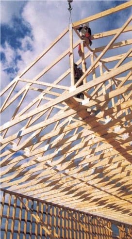
A truss is a structural frame relying on a triangular arrangement of webs and chords to transfer loads to reaction points. This geometric arrangement of the members gives trusses high strength-to-weight ratios, which permit longer spans than conventional framing. Light-frame truss can commonly span up to 20 m (60 ft), although longer spans are also feasible.

The first light-frame trusses were built on-site using nailed plywood gusset plates. These trusses offered acceptable spans but demanded considerable time to build. Originally developed in the United States in the 1950s, the metal connector plate transformed the truss industry by allowing efficient prefabrication of short and long span trusses. The light-gauge metal connector plates allow for the transfer of load between adjoining members through punched steel teeth that are embedded into the wood members. Today, light-frame wood trusses are widely used in single- and multi-family residential, institutional, agricultural, commercial and industrial construction.

The shape and size of light-frame trusses is restricted only by manufacturing capabilities, shipping limitations and handling considerations. Trusses can be designed as simple or multi-span and with or without cantilevers. Economy, ease of fabrication, fast delivery and simplified erection procedures make light-frame wood trusses competitive in many roof and floor applications. Their long span capability often eliminates the need for interior load bearing walls, offering the designer flexibility in floor layouts. Roof trusses offer pitched, sloped or flat roof configurations, while also providing clearance for insulation, ventilation, electrical, plumbing, heating and air conditioning services between the chords.

Light-frame wood trusses are prefabricated by pressing the protruding teeth of the steel truss plate into 38 mm (2 in) wood members, which are pre-cut and assembled in a jig. Most trusses are fabricated using 38 x 64 mm (2 x 3 in) to 38 x 184 mm (2 x 8 in) visually graded and machine stress-rated (MSR) lumber. To provide different grip values, the truss connector plates are stamped from galvanized light-gauge sheet steel of different grades and gauge thicknesses. Many sizes of truss plates are manufactured to suit any shape or size of truss or load to be carried.

Light frame trusses are manufactured according to standards established by the Truss Plate Institute of Canada. The capacities for the plates vary by manufacturer and are established through testing. Truss plates must conform to the requirements of CSA O86 and must be approved by the Canadian Construction Materials Centre (CCMC). To obtain approval, the truss plates are tested in accordance with CSA S347. During design, light-frame trusses are generally engineered by the truss plate manufacturer on behalf of the truss fabricator.

When light-frame trusses arrive at the job site they should be checked for any permanent damage such as cross breaks in the lumber, missing or damaged metal connector plates, excessive splits in the lumber, or any damage that could impair the structural integrity of the truss. Whenever possible, trusses should be unloaded in bundles on dry, relatively smooth ground. They should not be unloaded on rough terrain or uneven spaces that could result in undue lateral strain that could possibly distort the metal connector plates or damage parts of the trusses.

Light-frame trusses can be stored horizontally or vertically. If stored in the horizontal position, trusses should be supported on blocking spaced at 2.4 to 3 m (8 to 10 ft) centres to prevent lateral bending and reduce moisture gain from the ground. When stored in the vertical position, trusses should be placed on a stable horizontal surfaced and braced to prevent toppling or tipping. If trusses need to be stored for an extended period of time measures must be taken to protect them from the elements, keeping the trusses dry and well ventilated.

Light-frame trusses require temporary bracing during erection, prior to the installation of permanent bracing. Truss plates should not be used with incised lumber. Contact the truss manufacturer for further guidance on the use of light-frame trusses in corrosive environments, wet service conditions, or when treated with a fire retardant.

For further information, refer to the following resources:

Canadian Wood Truss Association

Truss Plate Institute of Canada

CSA O86 Engineering design in wood

CSA S347 Method of test for evaluation of truss plates used in lumber joints

Canadian Construction Materials Centre

Article

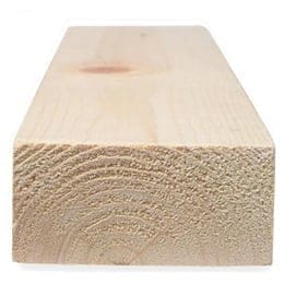
Dimension lumber is solid sawn wood that is less than 89 mm (3.5 in) in thickness. Lumber can be referred to by its nominal size in inches, which means the actual size rounded up to the nearest inch or by its actual size in millimeters. For instance, 38 × 89 mm (1-1/2 × 3-1/2 in) material is referred to nominally as 2 × 4 lumber. Air-dried or kiln dried lumber (S-Dry), having a moisture content of 19 percent or less, is readily available in the 38 mm (1.5 in) thickness. Dimension lumber thicknesses of 64 and 89 mm (2-1/2 and 3-1/2 in) are generally available as surfaced green (S-Grn) only, i.e., moisture content is greater than 19 percent.

The maximum length of dimension lumber that can be obtained is about 7 m (23 ft), but varies throughout Canada.

The predominant use of dimension lumber in building construction is in framing of roofs, floors, shearwalls, diaphragms, and load bearing walls. Lumber can be used directly as framing materials or may be used to manufacture engineered structural products, such as light frame trusses or prefabricated wood I-joists. Special grade dimension lumber called lamstock (laminating stock) is manufactured exclusively for glulam.

2x4 lumber board

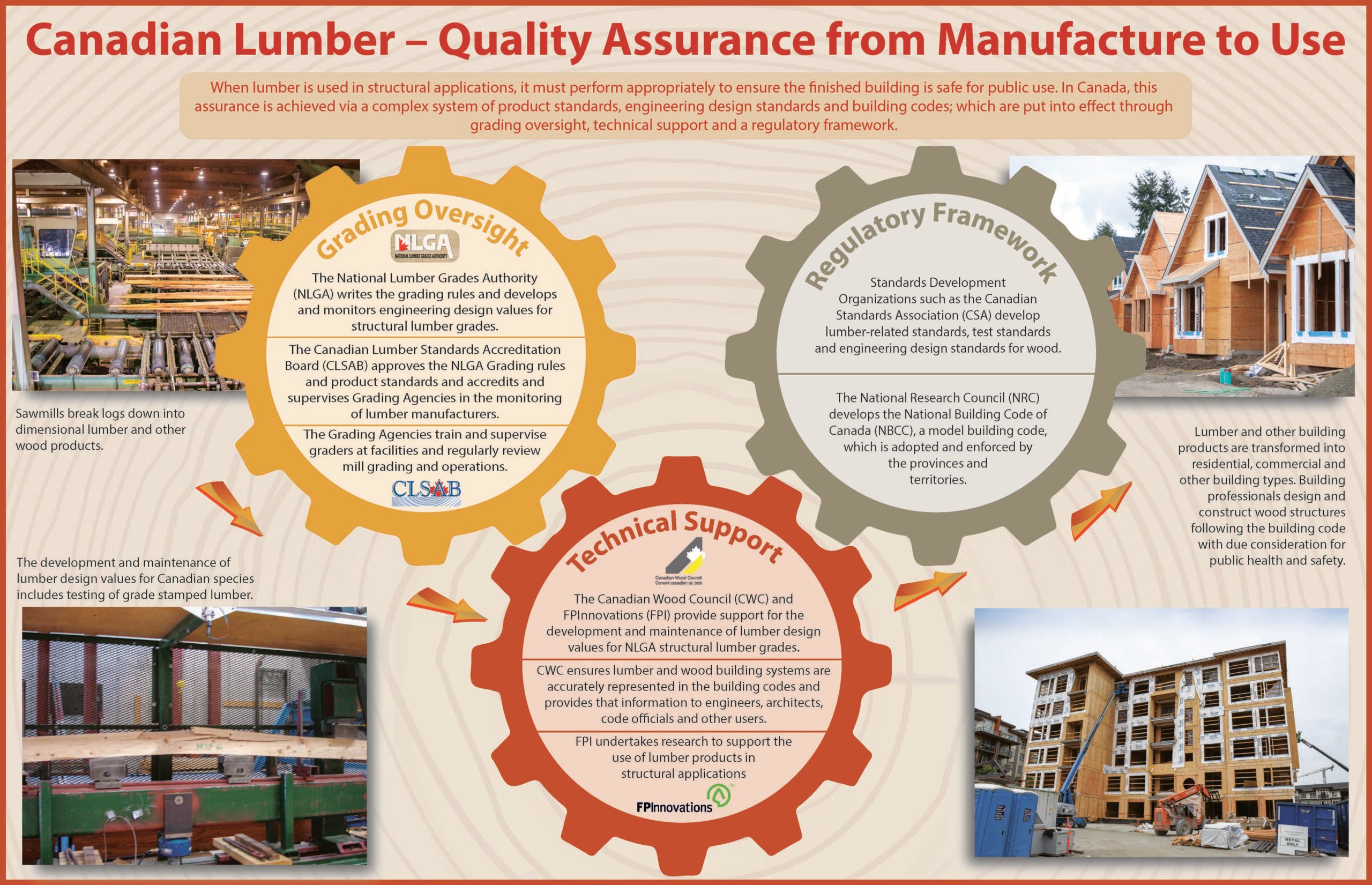
Quality assurance of Canadian lumber is achieved via a complex system of product standards, engineering design standards and building codes, involving grading oversight, technical support and a regulatory framework.

Checking and splitting
Fingerjoined Lumber
Lumber Sizes
Moisture content
Surface Smoothness

Article

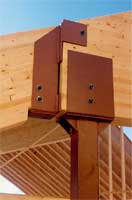
As for all other building materials, a critical aspect of wood structures is the manner by which members are connected. Wood products are building materials which are easily drilled, chiseled, or otherwise shaped to facilitate the connection of members, and a number of methods and a wide range of products are available for connecting wood. The installation of metal fasteners is the most common method of connecting wood products and a wide range of hardware is available. These range from the nails and the light connectors used for light framing construction to the bolts, side plates and other hardware used for heavy member connections. Each type of fastener is designed to be used with a particular type of construction.

For many applications, such as nailing for light-frame wall construction, metal fasteners serve only a structural purpose, and will be hidden from view by interior and exterior finishes. In other cases where wood members serve a structural purpose and are left exposed to add visual interest to a design and give a robust appearance to a structure, thought must be given to the connection layout and the selection and finishing of the wood products themselves. In other instances, where metal fasteners are exposed to view, the designer might want them to be as inconspicuous as possible. This can be done by selecting fasteners such as split rings and bolts, by reducing the visual impact of hardware through recessing it within the wood members, or by using painting to reduce the prominence of a connection.

1 2 3 4 5 6 7 8 9 10 11 12 13 14 15 16 17 18 19 20 21 22 23

Get Access to Our Resources

Stay in the loop and don’t miss a thing!

Filters

Persona Icon
Persona
Tags Icon
Tags
Annual Reports Plus Icon
Award Book Plus Icon
Case Studies Plus Icon
Free Publications Plus Icon
Magazine Plus Icon
Building Systems Plus Icon
Codes & Standards Plus Icon
Industry News Plus Icon
Why Wood (FAQ) Plus Icon
Wood Products Plus Icon
Acoustics Plus Icon
Design Examples Plus Icon
Engineering Plus Icon
Fire Resistance Plus Icon
Insurance Plus Icon
Mass Timber Plus Icon
Date Icon
Date
Line Separator