Welcome to the new CWC Digital Resource Hub

[dynamic_title_articles_tags]
266 results found...
Sort By Dropdown Icon
Article

Bolts are widely used in wood construction. They are able to resist moderately heavy loads with relatively few connectors.

Bolts may be used in wood-to-wood, wood-to-steel and wood-to-concrete connection types. Some typical structural applications for bolts include:

  • purlin to beam connections
  • beam to column connections
  • column to base connections
  • truss connections
  • timber arches
  • post and beam construction
  • pole-frame construction
  • timber bridges
  • marine structures

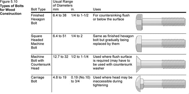
Several types of bolts as shown in Figure 5.10 below, are used for wood construction with the hexagon head type being the most common. Countersunk heads are used where a flush surface is desired. Carriage bolts can be tightened by turning the nut without holding the bolt since the shoulders under the head grip the wood.

Bolts are commonly available in imperial diameters of 1/4, 1/2, 5/8, 3/4, 7/8 and 1 inch. Bolts are installed in holes drilled slightly (1 to 2 mm) larger than the bolt diameter to prevent any splitting and stress development that could be caused by installation or subsequent wood shrinkage. Depending on the diameter, bolts are available in lengths from 75 mm (3″) up to 400 mm (16″) with other lengths available on special order.

Bolts can be dipped or plated, at an additional cost, to provide resistance to corrosion. In exposed conditions and high moisture environments, corrosion should be resisted by using hot dip galvanized or stainless steel bolts, washers and nuts.

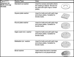
Washers are commonly used with bolts to keep the bolt head or nut from crushing the wood member when tightening is taking place. Washers are not required with a steel side plate, as the bolt head or nut bears directly on the steel. Common types of washers are shown in Figure 5.11 below.

Design information provided in CWC’s Wood Design Manual is based on bolts conforming to the requirements of ASTM A307 Standard Specification for Carbon Steel Bolts, Studs, and Threaded Rod 60 000 PSI Tensile Strength or Grade 2 bolts and dowels as specified under SAE J429 Mechanical and Material Requirements for Externally Threaded Fasteners.


Download Figure 5.10 (and 5.11) as a PDF.

Article

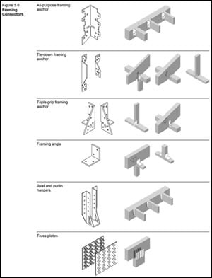
Framing connectors are proprietary products and include fastener types such as; framing anchors, framing angles, joist, purling and beam hangers, truss plates, post caps, post anchors, sill plate anchors, steel straps and nail-on steel plates. Framing connectors are often used for different reasons, such as; their ability to provide connections within prefabricated light-frame wood trusses, their ability to resist wind uplift and seismic loads, their ability to reduce the overall depth of a floor or roof assembly, or their ability to resist higher loads than traditional nailed connections. Examples of some common framing connectors are shown in Figure 5.6, below.

Framing connectors are made of sheet metal and are manufactured with pre-punched holes to accept nails. Standard framing connectors are commonly manufactured using 20- or 18-gauge zinc coated sheet steel. Medium and heavy-duty framing connectors can be made from heavier zinc-coated steel, usually 12-gauge and 7-gauge, respectively. The load transfer capacity of framing connectors is related to the thickness of the sheet metal as well as the number of nails used to fasten the framing connector to the wood member.

Framing connectors are suitable for most connection geometries that use dimensional lumber that is 38 mm (2″ nom.) and thicker lumber. In light-frame wood construction, framing connectors are commonly used in connections between joists and headers; rafters and plates or ridges; purlins and trusses; and studs and sill plates. Certain types of framing connectors, manufactured to fit larger wood members and carry higher loads, are also suitable for mass timber and post and beam construction.

Manufacturers of the framing connectors will specify the type and number of fasteners, along with the installation procedures that are required in order to achieve the tabulated resistance(s) of the connection. The Canadian Construction Materials Centre (CCMC), Institute for Research in Construction (IRC), produce evaluation reports that document resistance values of framing connectors, which are derived from testing results.


Figure 5.6 Framing Connectors


For more information, refer to the following resources:

Canadian Construction Material Centre, National Research Council of Canada

Truss Plate Institute of Canada

CSA S347 Method of Test for Evaluation of Truss Plates used in Lumber Joints

ASTM D1761 Standard Test Methods for Mechanical Fasteners in Wood

Canadian Wood Truss Association

Article

Nailing is the most basic and most commonly used means of attaching members in wood frame construction. Common nails and spiral nails are used extensively in all types of wood construction. Historical performance, along with research results have shown that nails are a viable connection for wood structures with light to moderate loads. They are particularly useful in locations where redundancy and ductile connections are required, such as loading under seismic events.

Typical structural applications for nailed connections include:

  • wood frame construction
  • post and beam construction
  • heavy timber construction
  • shearwalls and diaphragms
  • nailed gussets for wood truss construction
  • wood panel assemblies

Nails and spikes are manufactured in many lengths, diameters, styles, materials, finishes and coatings, each designed for a specific purpose and application.

In Canada, nails are specified by the type and length and are still manufactured to Imperial dimensions. Nails are made in lengths from 13 to 150 mm (1/2 to 6 in). Spikes are made in lengths from 100 to 350 mm (4 to 14 in) and are generally stockier than nails, that is, a spike has a larger cross-sectional area than an equivalent length common nail. Spikes are generally longer and thicker than nails and are generally used to fasten heavy pieces of timber.

Nail diameter is specified by gauge number (British Imperial Standard). The gauge is the same as the wire diameter used in the manufacture of the nail. Gauges vary according to nail type and length. In the U.S., the length of nails is designated by “penny” abbreviated “d”. For example, a twenty-penny nail (20d) has a length of four inches.

The most common nails are made of low or medium carbon steels or aluminum. Medium-carbon steels are sometimes hardened by heat treating and quenching to increase toughness. Nails of copper, brass, bronze, stainless steel, monel and other special metals are available if specially ordered. Table 1, below, provides examples of some common applications for nails made of different materials.

TABLE 1: Nail applications for alternative materials

Material Abbreviation Application
Aluminum A For improved appearance and long life: increased strain and corrosion resistance.
Steel – Mild S For general construction.
Steel – Medium Carbon Sc For special driving conditions: improved impact resistance.
Stainless steel, copper and silicon bronze E For superior corrosion resistance: more expensive than hot-dip galvanizing.


Uncoated steel nails used in areas subject to wetting will corrode, react with extractives in the wood, and result in staining of the wood surface. In addition, the naturally occurring extractives in cedars react with unprotected steel, copper and blued or electro-galvanized fasteners. In such cases, it is best to use nails made of non-corrosive material, such as stainless steel, or finished with non-corrosive material such as hot-dipped galvanized zinc. Table 2, below, provides examples of some common applications for alternative finishes and coatings of nails.

TABLE 2: Nail applications for alternative finishes and coatings

Nail Finish or Coating Abbreviation Application
Bright B For general construction, normal finish, not recommended for exposure to weather.
Blued Bl For increased holding power in hardwood, thin oxide finish produced by heat treatment.
Heat treated Ht For increased stiffness and holding power: black oxide finish.
Phoscoated Pt For increased holding power; not corrosion resistant.
Electro galvanized Ge For limited corrosion resistance; thin zinc plating; smooth surface; for interior use.
Hot-dip galvanized Ghd For improved corrosion resistance; thick zinc coating; rough surface; for exterior use.


Pneumatic or mechanical nailing guns have found wide-spread acceptance in North America due to the speed with which nails can be driven. They are especially cost effective in repetitive applications such as in shearwall construction where nail spacing can be considerably closer together. The nails for pneumatic guns are lightly attached to each other or joined with plastic, allowing quick loading nail clips, similar to joined paper staples. Fasteners for these tools are available in many different sizes and types.

Design information provided in CSA O86 is applicable only for common round steel wire nails, spikes and common spiral nails, as defined in CSA B111. The ASTM F1667 Standard is also widely accepted and includes nail diameters that are not included in the CSA B111. Other nail-type fastenings not described in CSA B111 or ASTM F1667 may also be used, if supporting data is available.

Types of Nails 

For more information, refer to the following resources:

International, Staple, Nail, and Tool Association (ISANTA)

CSA O86 Engineering design in wood

CSA B111 Wire Nails, Spikes and Staples

ASTM F1667 Standard Specification for Driven Fasteners: Nails, Spikes and Staples

Article

Wood Screws

Wood screws are manufactured in many different lengths, diameters and styles. Wood screws in structural framing applications such as fastening floor sheathing to the floors joists or the attachment of gypsum wallboard to wall framing members. Wood screws are often higher in cost than nails due to the machining required to make the thread and the head.

Screws are usually specified by gauge number, length, head style, material and finish. Screw lengths between 1 inch and 2 ¾ inch lengths are manufactured in ¼ inch intervals, whereas screws 3 inches and longer, are manufactured in ½ inch intervals. Designers should check with suppliers to determine availability.

Design provisions in Canada are limited to 6, 8, 10 and 12 gauge screws and are applicable only for wood screws that meet the requirements of ASME B18.6.1. For wood screw diameters greater than 12 gauge, design should be in accordance with the lag screw requirements of CSA O86.

Screws are designed to be much better at resisting withdrawal than nails. The length of the threaded portion of the screw is approximately two-thirds of the screw length. Where the wood relative density is equal to or greater than 0.5, lead holes, at least the length of the threaded portion of the shank, are required. In order to reduce the occurrence of splitting, pre-drilled holes are recommended for all screw connections.

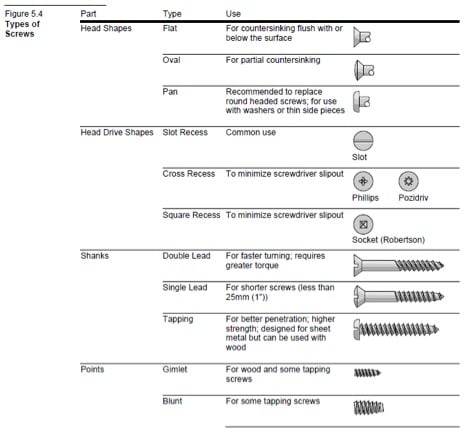
The types of wood screws commonly used are shown in Figure 5.4, below.

For more information on wood screws, refer to the following resources:

ASME B18.6.1 Wood Screws

CSA O86 Engineering design in wood

Article

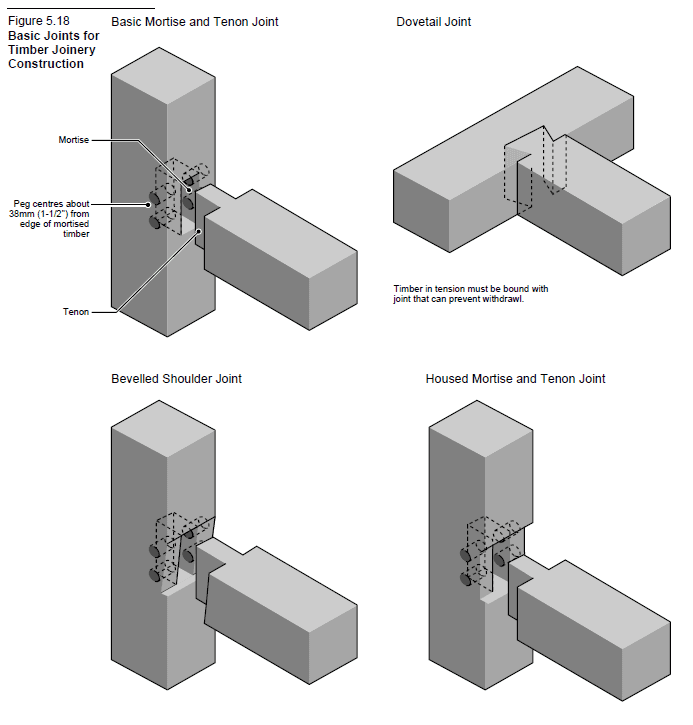
Many historic structures in North America were built at a time when metal fasteners were not readily available. Instead, wood members were joined by shaping the adjoining wood members to interlock with one another. Timber joinery is a traditional post and beam wood construction technique used to connect wood members without the use of metal fasteners.

Timber joinery requires that the ends of timbers are carved out so that they fit together like puzzle pieces. The variations and configurations of wood-to-wood joints is quite large and complex. Some common wood-to-wood timber joints include mortise and tenon, dovetail, tying joint, scarf joint, bevelled shoulder joint, and lap joint. There are many variations and combinations of these and other types of timber joinery. Refer to Figure 5.18, below, for some examples of timber joinery.

For load transfer, timber joinery relies upon the interlocking of adjoining wood members. The mated joints are restrained by inserting wooden pegs into holes bored through the interlocked members. A hole about an inch in diameter is drilled right through the joint, and a wooden peg is pounded in to hold the joint together.

Metal fasteners require only minimal removal of wood fibre in the area of the fasteners and therefore, the capacity of the system is often governed by the moderate sized wood members to carry horizontal and vertical loads. Timber joinery, on the contrary, requires the removal of a significant volume of wood fibre where joints occur. For this reason, the capacity of traditional timber joinery construction is usually governed by the connections and not by the capacity of the members themselves. To accommodate for the removal of wood fibre at the connection locations, member sizes of wood construction systems that employ timber joinery, such as post and beam construction, are often larger than wood construction systems that make use of metal fasteners.

Wood engineering design standards in Canada do not provide specific load transfer information for timber joinery due to their sensitivity to workmanship and material quality. As a result, engineering design must be conservative, often resulting in larger member sizes.

The amount of skill and time required for measuring, fitting, cutting, and trial assembly is far greater for timber joinery than for other types of wood construction. Therefore, it is not the most economical means of connecting the members of wood buildings. Timber joinery is not used where economy is the overriding design criteria. Instead, it is used to provide a unique structural appearance which portrays the natural beauty of wood without distraction. Timber joinery offers a unique visual appearance exhibiting a high degree of craftmanship.


For further information, refer to the following resources:

Timber Framers Guild


Article

Oriented Strand Board (OSB) is a widely used, versatile structural wood panel. OSB makes efficient use of forest resources, by employing less valuable, fast-growing species. OSB is made from abundant, small diameter poplar and aspen trees to produce an economical structural panel. The manufacturing process can make use of crooked, knotty and deformed trees which would not otherwise have commercial value, thereby maximizing forest utilization.

OSB has the ability to provide structural performance advantages, an important component of the building envelope and cost savings. OSB is a dimensionally stable wood-based panel that has the ability to resist delamination and warping. OSB can also resist racking and shape distortion when subjected to wind and seismic loadings. OSB panels are light in weight and easy to handle and install.

OSB panels are primarily used in dry service conditions as roof, wall and floor sheathing, and act as key structural components for resisting lateral loads in diaphragms and shearwalls. OSB is also used as the web material for some types of prefabricated wood I-joists and the skin material for structural insulated panels. OSB can also be used in siding, soffit, floor underlayment and subfloor applications. Some specialty OSB products are made for siding and for concrete formwork, although OSB is not commonly treated using preservatives. OSB has many interleaved layers which provide the panel with good nail and screw holding properties. Fasteners can be driven as close as 6 mm (1/4 in) from the panel edge without risk of splitting or breaking out.

OSB is a structural mat-formed panel product that is made from thin strands of aspen or poplar, sliced from small diameter roundwood logs or blocks, and bonded together with a waterproof phenolic adhesive that is cured under heat and pressure. OSB is also manufactured using the southern yellow pine species in the United States. Other species, such as birch, maple or sweetgum can also be used in limited quantities during manufacture.

OSB is manufactured with the surface layer strands aligned in the long panel direction, while the inner layers have random or cross alignment. Similar to plywood, OSB is stronger along the long axis compared to the narrow axis. This random or cross orientation of the strands and wafers results in a structural engineered wood panel with consistent stiffness and strength properties, as well as dimensional stability. It is also possible to produce directionally-specific strength properties by adjusting the orientation of strand or wafer layers. The wafers or strands used in the manufacture of OSB are generally up to 150 mm (6 in) long in the grain direction, 25 mm (1 in) wide and less than 1 mm (1/32″) in thickness.

In Canada, OSB panels are manufactured to meet the requirements of the CSA O325 standard. This standard sets performance ratings for specific end uses such as floor, roof and wall sheathing in light-frame wood construction. Sheathing conforming to CSA O325 is referenced in Part 9 of the National Building Code of Canada (NBC). In addition, design values for OSB construction sheathing are listed in CSA O86, allowing for engineering design of roof sheathing, wall sheathing and floor sheathing using OSB conforming to CSA O325.

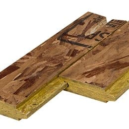
OSB panels are manufactured in both imperial and metric sizes, and are either square-edged or tongue-and-grooved on the long edges for panels 15 mm (19/32 in) and thicker. For more information on available sizes of OSB panel, refer to the document below.

For more information on OSB, please refer to the following resources:

APA – The Engineered Wood Association

National Building Code of Canada

CSA O86 Engineering design in wood

CSA O325 Construction sheathing

CSA O437 Standards on OSB and Waferboard

PFS TECO

Example specifications for oriented strand board (OSB)
Oriented Strand Board (OSB) Grades
Oriented Strand Board (OSB) Manufacture
Oriented Strand Board (OSB) Quality Control
Oriented Strand Board (OSB) Sizes
Oriented Strand Board (OSB) Storage and Handling

Article

Plywood is a widely recognized engineered wood-based panel product that has been used in Canadian construction projects for decades. Plywood panels manufactured for structural applications are built up from multiple layers or plys of softwood veneer that are glued together so that the grain direction of each layer of veneer is perpendicular to that of the adjacent layers. These cross-laminated sheets of wood veneer are bonded together with a waterproof phenol-formaldehyde resin adhesive and cured under heat and pressure.

Plywood panels have superior dimensional stability, two-way strength and stiffness properties and an excellent strength-to-weight ratio. They are also highly resistant to impact damage, chemicals, and changes in temperature and relative humidity. Plywood remains flat to give a smooth, uniform surface that does not crack, cup or twist. Plywood can be painted, stained, or ordered with factory applied stains or finishes. Plywood is available with squared or tongue and groove edges, the latter of which can help to reduce labour and material costs by eliminating the need for panel edge blocking in certain design scenarios.

Plywood is suitable for a variety of end uses in both wet and dry service conditions, including: subflooring, single-layer flooring, wall, roof and floor sheathing, structural insulated panels, marine applications, webs of wood I-joists, concrete formwork, pallets, industrial containers, and furniture.

Plywood panels used as exterior wall and roof sheathing perform multiple functions; they can provide resistance to lateral forces such as wind and earthquake loads and also form an integral component of the building envelope. Plywood may be used as both a structural sheathing and a finish cladding. For exterior cladding applications, specialty plywoods are available in a broad range of patterns and textures, combining the natural characteristics of wood with superior strength and stiffness properties. When treated with wood preservatives, plywood is also suitable for use under extreme and prolonged moisture exposure such as permanent wood foundations.

Plywood is available in a wide variety of appearance grades, ranging from smooth, natural surfaces suitable for finish work to more economical unsanded grades used for sheathing. Plywood is available in more than a dozen common thicknesses and over twenty different grades.

Unsanded sheathing grade Douglas Fir Plywood (DFP), conforming to CSA O121, and Canadian Softwood Plywood (CSP), conforming to CSA O151, are the two most common types of softwood plywoods produced in Canada. All structural plywood products are marked with a legible and durable grade stamp that indicates: conformance to either CSA O121, CSA O151 or CSA O153, the manufacturer, the bond type (EXTERIOR), the species (DFP) or (CSP), and the grade.

Plywood can be chemically treated to improve resistance to decay or to fire. Preservative treatment must be done by a pressure process, in accordance with CSA O80 standards. It is required that plywood manufacturers carry out testing in conformance with ASTM D5516 and ASTM D6305 to determine the effects of fire retardants, or any other potentially strength-reducing chemicals.


For further information, refer to the following resources:

APA – The Engineered Wood Association

CSA O121 Douglas fir plywood,

CSA O151 Canadian softwood plywood

CSA O153 Poplar plywood

CSA O86 Engineering design in wood

CSA O80 Wood preservation

ASTM D5516 Standard Test Method for Evaluating the Flexural Properties of Fire-Retardant Treated Softwood Plywood Exposed to Elevated Temperatures

ASTM D6305 Standard Practice for Calculating Bending Strength Design Adjustment Factors for Fire-Retardant-Treated Plywood Roof Sheathing

National Building Code of Canada

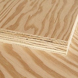
corner of a plywood sheet showing thickness

Example Specifications for Plywood
Plywood Grades
Plywood Handling and Storage
Plywood Manufacture
Plywood Sizes
Quality Control of Plywood

Article


*The Effective R Calculator tool is fully optimized for best performance in Google Chrome.

The purpose of this R Value online tool is to provide designers with climate zone-appropriate insulated wall assembly solutions that are easily comparable with national and provincial energy efficiency prescriptive provisions.

Each assembly lists:

  • Effective thermal resistance Reff* for complying with the National Building Code (NBC) for houses and the National Energy Code for Buildings (NECB) for larger buildings
  • Installed R-value for complying with the Ontario Building Code
  • Centre of cavity R-value for complying with the Quebec Construction Code.

*The calculation of effective thermal resistance is performed in compliance with NBC Subsection 9.36.5. of Division B.

Each assembly comes with a climate-specific colour-coded durability assessment, which has been determined considering computer analysis and field experience by building science experts in Canada.

assembled frame wall icon - R Value wall thermal design catalogue List of Available Wall Assemblies question mark icon How to Use the Effective R Calculator
book icon Canadian Code Requirements for Above Grade Wall Thermal Design notepad icon Understanding the Builder Notes
icon of thermometer with plug Wall Thermal Design Performance Literature: Excerpts from the CHBA Manual thumb up icon Understanding the Building Science Durability Notes

ACKNOWLEDGEMENTS

Many thanks to the steering committee and project team for making this online tool possible:

Steering Committee

Alejandra Nieto ROCKWOOL
Ben Hawken Mattamy Homes Limited
BJ Yeh APA – The Engineered Wood Association
Bob Wilson R.S. Wilson Building Inspection & Consulting Inc.
Bruce West City of Brampton
Christopher McLellan Natural Resources Canada
Cory McCambridge APA – The Engineered Wood Association
Dave Henderson Brookfield Homes
David Silburn SAIT Green Building Technologies
Gillian Haley ERA Architects Inc.
Jason Shapardanis Empire Communities
Jieying Wang FPInnovations
John Hockman JLHockman Consulting Inc.
Kelsey Saunders Sustainable.TO
Louis Previte Great Gulf Homes
Paul Smith Mattamy Homes Corporation
Peter Birkbeck Icynene Inc.
Peter Culyer EIFS Council of Canada
Richard Kadulski Solplan Review
Rick Gratton Brookfield Residencial Properties Inc.
Rick Roos ROCKWOOL
Robert Marshall CertainTeed SAINT-GOBAIN
Salvatore Ciarlo Owens Corning Canada
Silvio Plescia Canada Mortgage and Housing Corporation
Steve Doty Empire Communities
Todd Rogers City of St. Catharines
To join the committee or to discuss inclusion of more products in the tool, please contact Robert Jonkman – [email protected]


Project Team

Project Initiator Robert Jonkman Canadian Wood Council
Project Lead Michael Lio buildABILITY Corportation
Project Manager and Publishing Expert Francesca Cuda buildABILITY Corporation
Builder Lead and Field Expert Andy Oding Building Knowledge Canada
Technical Lead and Building Science Expert Chris Timusk Timusk Consulting, George Brown College
Technical Project Advisor Gord Cooke Building Knowledge Canada
WUFI Expert Panelist Graham Finch RDH Consulting
WUFI Expert Panelist Chris Schumacher RDH Consulting
Article

Are you interested in learning about the carbon benefits of your wood building? After inputting wood volumes, the tool estimates how much time it takes Canadian and U.S. forests to grow that volume of wood along with the associated carbon benefits – both the amount of carbon stored and the amount of greenhouse gas emissions avoided. Follow the instructions on each input tab of this easy-to-use calculator tool to find out the estimated carbon benefits of your building project.

Article

Understanding the Simulated Durability Analysis Results


WUFI Hygrothermal Modeling and Field Experience Rating
This represents the result of a combined analysis of field experience and comprehensive WUFI analyses on the selected wall assembly in each of the 5 climate conditions:

Dark Green square from R Calculator indicates High PassDark Green: HIGH PASS

Field: Good experience under wide range of conditions
Physics: Well understood physics and sound basis for design
Hygrothermal Modelling: Simulations support field experience and expectations from physics
Green square from R CalculatorLight Green: PASS

Field: Good experience under normal conditions
Physics: Well understood physics; expected to  be slightly sensitive to details and workmanship
Hygrothermal Modelling: Simulations support field experience and expectations from physics
yellow square from R CalculatorYellow: CONDITIONAL PASS

Field: Acceptable experience under  normal conditions; more sensitive to details, workmanship, and microclimates
Physics: More complex physics, expected to be more sensitive to details and workmanship
Hygrothermal Modelling: Field experience and physics can only be explained by expert modellers
orange square from R CalculatorOrange: CONDITIONAL FAIL

Field: Demonstrated to be risky in certain situations
Physics: More complex physics, expected to be VERY sensitive to details and workmanship
Hygrothermal Modelling: Field experience and physics can only be explained by expert modellers

Building Codes have air barrier and rain intrusion requirements that are assumed to be complied with.  Failure to meet code requirements can result in walls that are not durable.

It is important to note that all the assemblies were simulated assuming no air leakage and no water intrusion/leakage.  As a result, the WUFI durability simulations do not consider the limited drying potential associated with the use of low permeance sheathing materials when combined with poor air barrier installation and flashing details.

Please see WUFI Assumptions for more details.

Outboard to Inboard Ratio Compliance
This scale represents the result of an outboard to inboard analysis on the wall assemblies using low permeance exterior sheathings:

green squareGreen indicates that the wall meets the climate’s required minimum ratio
red squareRed indicates that the wall does not meet the climate’s required minimum ratio and the outboard sheathing’s permeance must be examined to verify Code compliance
Article

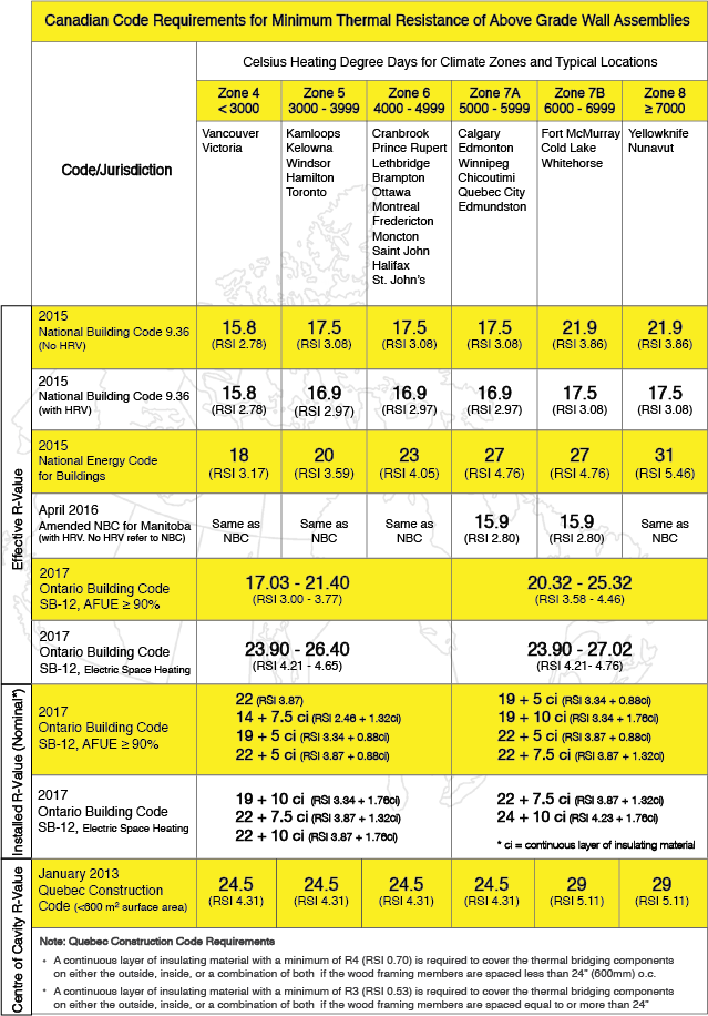
Canadian R Value Code Requirements

Code Table

Last updated: January 2017

DISCLAIMER: The Canadian Wood Council’s Wall Thermal Design Calculator has been developed for information purposes only. Reference should always be made to the Building Code having jurisdiction. This tool should not be relied upon as a substitute for legal or design advice, and the user is responsible for how the tool is used or applied.

Article

Most building envelope / building enclosure failures can be traced back to water. If we can learn to manage (rather than control) water in the building envelope/enclosure, we will have learned how to master an essential component of building science. We have deliberately chosen the term “manage” since it implies using the laws of nature to our advantage rather than attempting to conquer nature by brute force. Attempts to control water movement by face sealing walls, for example, require perfect materials, workership and maintenance,  commodities which are rarely available to us. Management on the other hand implies designing assemblies which can deflect, drain, store and dry moisture, using materials suited to the various microclimates which the outside climate, inside climate and wall construction provide.

In the building science context, the transport of water can be divided into three main categories:

  1. water transported through porous materials by water vapour diffusion, either from the inside or from the outside
  2. water vapour carried by moving air, and
  3. liquid or bulk water from rain, wind driven rain, melting snow, groundwater driven by gravity or kinetic energy

Water Vapour Diffusion

The rate of water vapour diffusion through a porous material is determined by a water vapour pressure gradient (or water vapour molecule concentration gradient) from one side to the other side of the material, and the permeance of the material given in “perms” in the U.S. or ng/pa.s.m2 in Canada (1 perm = 57 ng/pa.s.m2). The greater the water vapour pressure gradient, the greater the rate of diffusion. The greater the permeance, the greater the rate of diffusion.

These Durability Notes will focus on two types or categories of vapour diffusion: Water Vapour Diffusion from Inside, and Water Vapour Diffusion from the Outside. Additionally, categories include air leakage from the inside, exterior moisture/wetting and drying potential to the outside and to the inside. 

Water vapour diffusion from the inside is typically a wintertime phenomenon in cold climates, and can be managed by either maintaining the indoor relative humidity (rh) at a safe level (CMHC recommends a maximum of 40 to 50% indoor rh in the winter time). 
Water Vapour Diffusion from Outside is typically a late spring, summer or early fall phenomenon in a cold climate, and is usually of a specific category known as “solar-driven moisture”  when it presents moisture related problems. Solar driven moisture is happens when a porous cladding capable of absorbing and storing water (such as a brick veneer or wood siding) becomes wet due to a rain event, and then the sun shines on the wall cladding, heating it up often up to over 40ºC above the ambient air temperature, resulting in very high vapour pressures within the porous cladding, which then drives the water vapour into the wall. This phenomenon is most common on east and west elevations as these receive the maximum solar exposure in the summer.  Some common methods for avoiding this phenomenon involve using non-absorptive claddings such as vinyl siding or non-absorptive treatments on wood siding, by providing a well vented cavity vented to the outside behind brick veneers and other absorptive claddings, or by providing shading to east and west facing walls.
Air Leakage Transported Moisture from Inside is typically a wintertime phenomenon in cold climates, and can typically cause greater moisture related problems than water vapour diffusion. This phenomenon occurs when warm, moisture laden interior air is not prevented from leaking into a building assembly, and comes in contact with a cold, low permeability material which is at a temperature below the dew point temperature of the indoor air, where the moisture then condenses on the cold surface. If this moisture cannot be drained away and accumulates it may result in mould, rot, corrosion etc. This phenomenon can be prevented in several ways and combinations of ways, including the use of continuous interior air barriers (eg. taped drywall with all penetrations sealed, polyethylene air barriers/vapour retarders), by designing the assembly such that the first air-tight material in the assembly is at a temperature above the dew point temperature of the indoor air (eg.using  Insulative exterior sheathing), by using materials which are not moisture susceptible, and by maintaining a safe indoor wintertime relative humidity.
Exterior Moisture/Wetting (Rain) can present problems either when the water can penetrate/leak into an assembly where it comes in contact with and accumulates in/on moisture-susceptible materials, (made worse by rain in combination with wind, called wind-driven rain), or when the rain comes in contact with susceptible claddings for extended periods of time (again made worse by wind-driven rain). Walls facing the prevailing wind for a given region are at highest risk. Rain falling straight down without wind can be relatively easily dealt with by providing adequate roof-overhangs, eaves troughs and flashings, and by using cladding materials which are not susceptible to moisture related problems. Wind-driven rain is more difficult to deal with, but the same approaches apply. In addition, it should always be assumed that at some point in time, water will penetrate into an assembly, and it must be allowed to get back out by the use of flashings and drainage planes, by allowing drying to both sides if possible, and by using materials not susceptible to moisture related damage.
Drying Potential to the Inside and to the Outside can occur in building assemblies. However, to avoid deterioration of the wall or wetting of the building interior, moisture from within the assembly will need to effectively dry to the inside and/or to the outside. Excess moisture can move into the assembly from the interior or from the exterior. Moisture can also be built into the assembly when wet materials or components are used at the time of construction. Assemblies that get wet and that are able to dry are generally more durable than otherwise.

Deterioration Mechanisms

  • Mould
  • Rot
  • Corrosion
  • Freeze-thaw

Understanding the Simulated Durability Analysis Results


WUFI Hygrothermal Modeling and Field Experience Rating
This represents the result of a combined analysis of field experience and comprehensive WUFI analyses on the selected wall assembly in each of the 5 climate conditions:

dark green square that represents High Pass rating for durabilityDark Green: HIGH PASS

Field: Good experience under wide range of conditions
Physics: Well understood physics and sound basis for design
Hygrothermal Modelling: Simulations support field experience and expectations from physics
green square that represents a Pass rating for durabilityLight Green: PASS

Field: Good experience under normal conditions
Physics: Well understood physics; expected to  be slightly sensitive to details and workmanship
Hygrothermal Modelling: Simulations support field experience and expectations from physics
yellow square that represents conditional Pass rating for durabilityYellow: CONDITIONAL PASS

Field: Acceptable experience under  normal conditions; more sensitive to details, workmanship, and microclimates
Physics: More complex physics, expected to be more sensitive to details and workmanship
Hygrothermal Modelling: Field experience and physics can only be explained by expert modellers
orange square that represents a Fail rating for durabilityOrange: CONDITIONAL FAIL

Field: Demonstrated to be risky in certain situations
Physics: More complex physics, expected to be VERY sensitive to details and workmanship
Hygrothermal Modelling: Field experience and physics can only be explained by expert modellers

Building Codes have air barrier and rain intrusion requirements that are assumed to be complied with.  Failure to meet code requirements can result in walls that are not durable.

It is important to note that all the assemblies were simulated assuming no air leakage and no water intrusion/leakage.  As a result, the WUFI durability simulations do not consider the limited drying potential associated with the use of low permeance sheathing materials when combined with poor air barrier installation and flashing details.

Please see WUFI Assumptions for more details.

Outboard to Inboard Ratio Compliance
This scale represents the result of an outboard to inboard analysis on the wall assemblies using low permeance exterior sheathings:

green squarePASS – Green indicates that the wall meets the climate’s required minimum ratio
red squareFAIL – Red indicates that the wall does not meet the climate’s required minimum ratio and the outboard sheathing’s permeance must be examined to verify Code compliance
1 2 3 4 5 6 7 8 9 10 11 12 13 14 15 16 17 18 19 20 21 22 23

Get Access to Our Resources

Stay in the loop and don’t miss a thing!

Filters

Persona Icon
Persona
Tags Icon
Tags
Annual Reports Plus Icon
Award Book Plus Icon
Case Studies Plus Icon
Free Publications Plus Icon
Magazine Plus Icon
Building Systems Plus Icon
Codes & Standards Plus Icon
Industry News Plus Icon
Why Wood (FAQ) Plus Icon
Wood Products Plus Icon
Acoustics Plus Icon
Design Examples Plus Icon
Engineering Plus Icon
Fire Resistance Plus Icon
Insurance Plus Icon
Mass Timber Plus Icon
Date Icon
Date
Line Separator